Analysis and Synthesis of Logic Functions using Decoders 
Procedure
Please follow these steps to do the experiment.
Part 1:
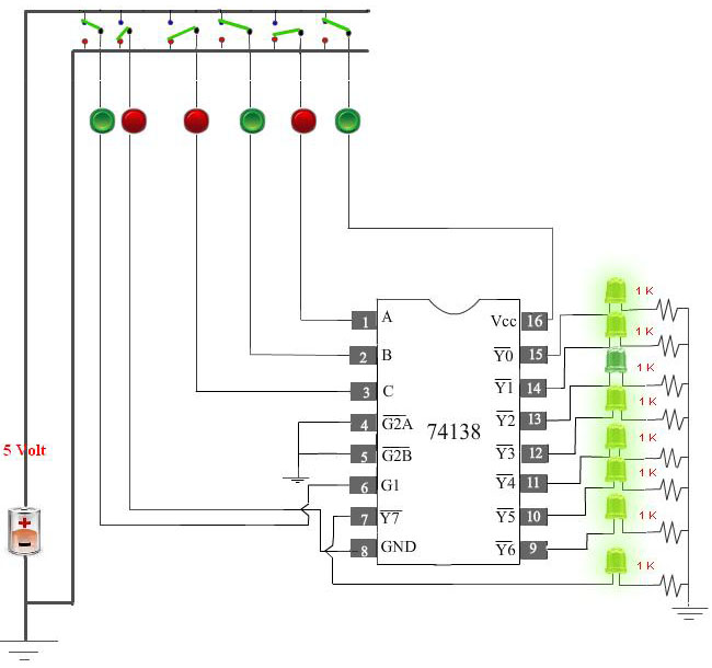
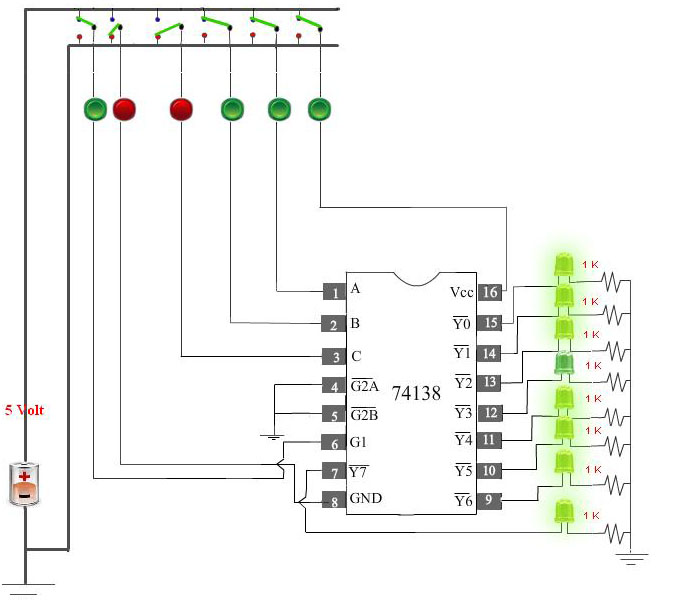
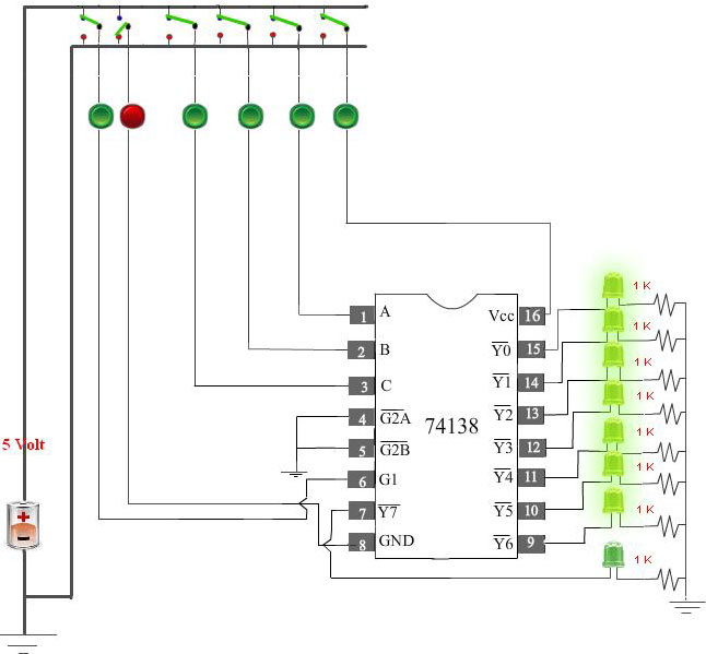
- At first go through the structure of 74138. Then apply high level voltage to VCC and apply low level voltage to GND and also apply high level voltage to G1.
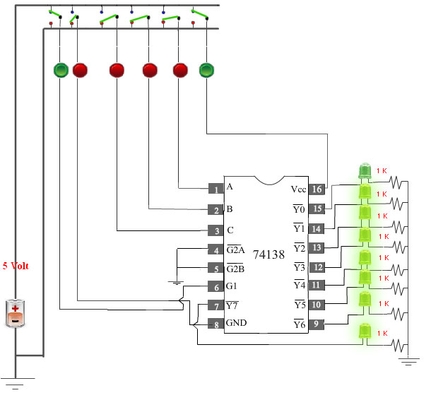
- Next, apply low level voltage to all the three select inputs (C B A). Now check that Y0 is at low state. Other outputs are at high state.
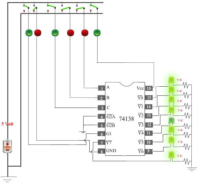
- Next, apply low level voltage to C and B and apply high level voltage to A.Now check that Y1 is at low state. Other outputs are at high state.
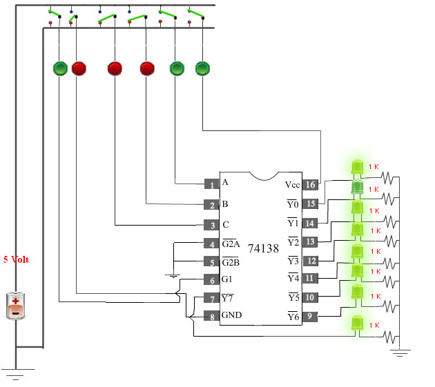
- Next, apply low level voltage to C and A and apply high level voltage to B.Now check that Y2 is at low state. Other outputs are at high state.
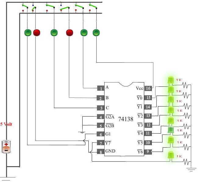
- Next, apply low level voltage to C and apply high level voltage to B and A. Now check that Y3 is at low state. Other outputs are at high state.
- Next, apply high level voltage to C and apply low level voltage to B and A. Now check that Y4 is at low state. Other outputs are at high state.
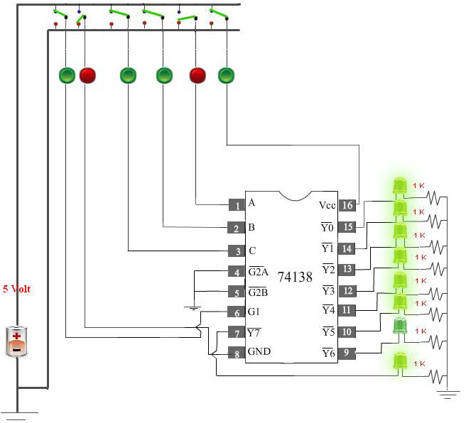
- Next, apply high level voltage to C and A and apply low level voltage to B.Now check that Y5 is at low state. Other outputs are at high state.
- Next, apply high level voltage to C and B high and apply low level voltage to A. Now check that Y6 is at low state. Other outputs are at high state.
- Next, apply high level voltage to all the select inputs (C,B,A). Now check that Y7 is at low state. Other outputs are at high state.
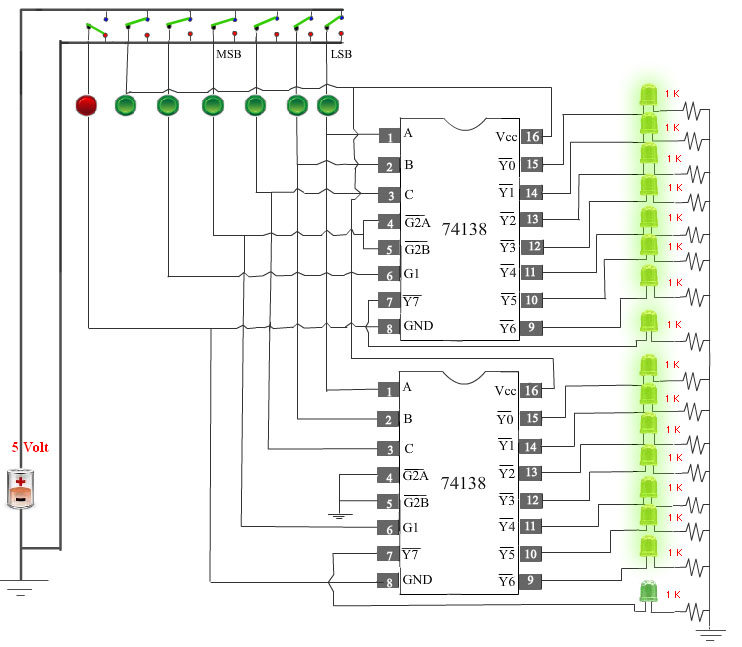
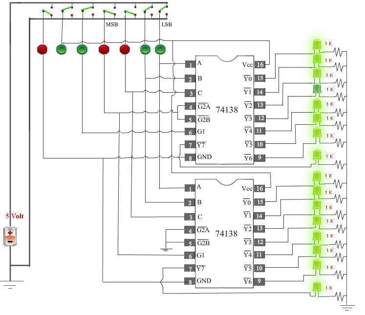
Please follow these steps to do the experiment(Part2).
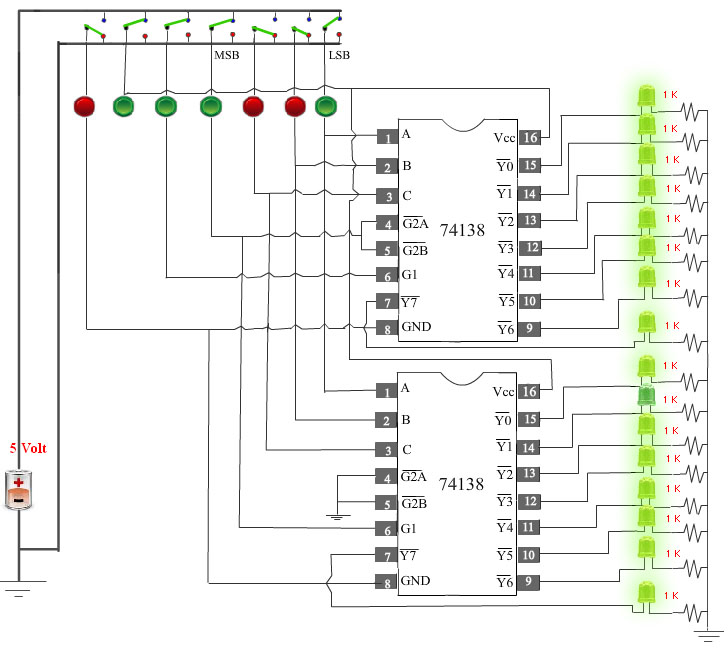
- At first apply high level voltage to VCC and apply low level voltage to GND andapply high level voltage to G1 input of 1st decoder.
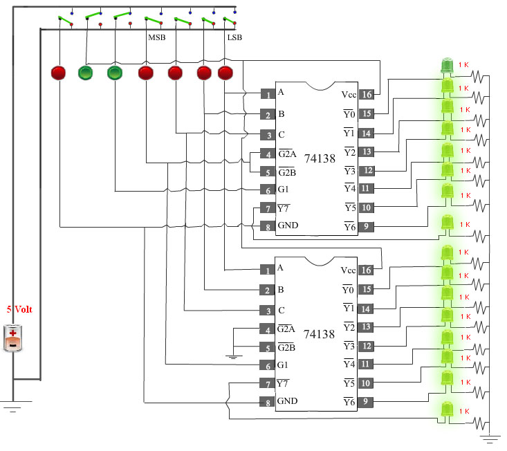
- Next, apply low level voltage to all the four select inputs (MSB,C B A).Now check that Y0 (1st Decoder) is at low state. Other outputs are at high state.
- Next, apply high level voltage to A and apply low level voltage to all other select inputs (MSB,C B).Now check that Y1 (1st Decoder) is at low state. Other outputs are at high state.
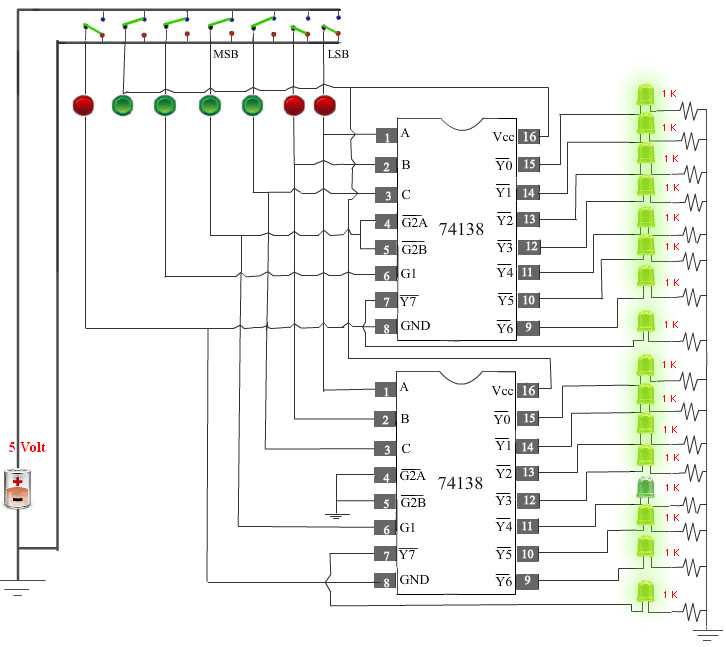
- Next, apply high level voltage to B and apply low level voltage to all other select inputs (MSB,C, A ). Now check that Y2 (1st Decoder) is at low state. Other outputs are at high state.
- Next, apply high level voltage to A and B and apply low level voltage to all other select inputs (MSB,C )low. Now check that Y3 (1st Decoder) is at low state. Other outputs are at high state.
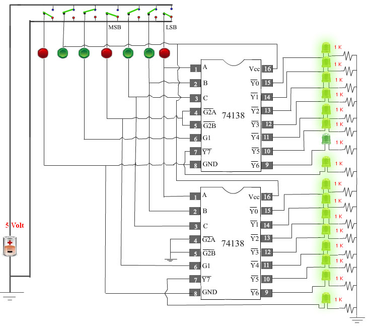
- Next, apply high level voltage to C and apply low level voltage to all other select inputs (MSB,B,A ). Now check that Y4 (1st Decoder) is at low state. Other outputs are at high state.
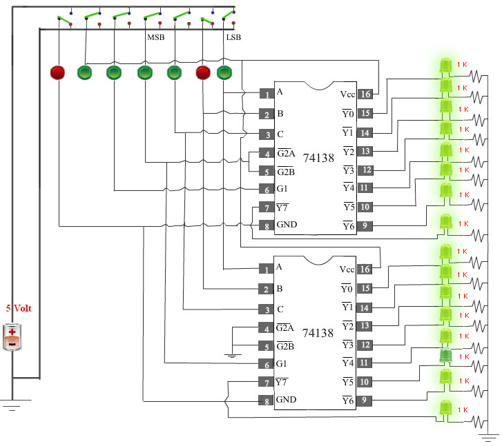
- Next, apply high level voltage to C and A and apply low level voltage to all other select inputs (MSB,B ).Now check that Y5 (1st Decoder) is at low state. Other outputs are at high state.

- Next, apply high level voltage to C and B and apply low level voltage to all other select inputs (MSB,A ). Now check that Y6 (1st Decoder) is at low state. Other outputs are at high state.
- Next, apply high level voltage to C , B and A high and apply low level voltage to (MSB)input. Now check that Y7 (1st Decoder) is at low state. Other outputs are at high state.

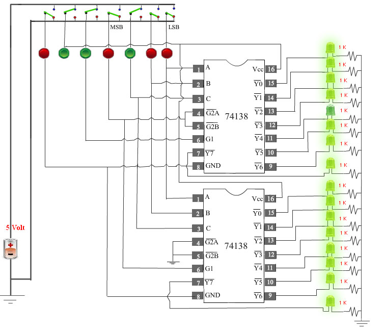
- Next, apply high level voltage to MSB and apply low level voltage to all other select inputs (C,B,A). Now check that Y0 (2nd Decoder) is at low state. Other outputs are at high state.
- Next, apply high level voltage to MSB and A and apply low level voltage to all other select inputs (C,B). Now check that Y1(2nd Decoder) is at low state. Other outputs are at highstate.
- Next, apply high level voltage to MSB and B and apply low level voltage to all other select inputs(C,A). Now check that Y2 (2nd Decoder) is at low state. Other outputs are at high state.

- Next, apply high level voltage to MSB , B and A and apply low level voltage to the input (C). Now check that Y3 (2nd Decoder) is at low state. Other outputs are at high state.

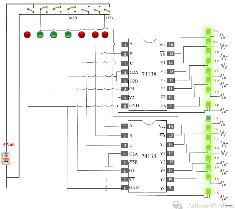
- Next, apply high level voltage to MSB and C and apply low level voltage to all other select inputs (B,A). Now check that Y4 (2nd Decoder) is at low state. Other outputs are at high state.
- Next, apply high level voltage to MSB , C and A and apply low level voltage to the select input (B). Now check that Y5 (2nd Decoder) is at low state. Other outputs are at high state.
- Next, apply high level voltage to MSB , C and B and apply low level voltage to the input (A).Now check that Y6 (2nd Decoder) is at low state. Other outputs are at high state.
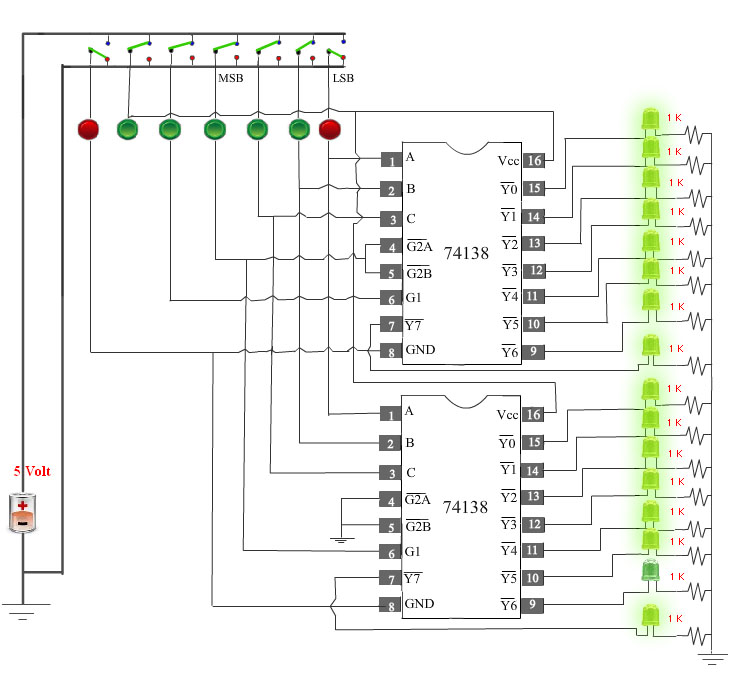
- Next, apply high level voltage to all the select inputs (MSB,C,B,A). Now check that Y7 (2nd Decoder) is at low state. Other outputs are at high state.