Analysis and Synthesis of Sequential Circuits using J-K Flip-Flops
INSTRUCTION
- Apply \(V_{CC1 }\) and \(V_{CC2}\), so that clock start button will be enabled. Apply low level voltage to ground(GND1) and (GND2).
- Next, start the clock pulse by clicking on the "Clock Start" button and after generation of some clock pulses stop the clock pulse by clicking on the"clock Stop" button .
- Now apply high voltage to J input and low voltage to K input and set "No of clock pulses" to 1. See the changes at output(Q and Q) at positive clock edge.
- Now apply high voltage to K input and low voltage to J input and start the clock pulse. See the changes at output(Q and Q) at positive clock edge.
- Next,apply low voltage to both the inputs(J and K) and see the changes at output(Q and Q) at positive clock edge.
- Next,apply high voltage to both the inputs(J and K) and start the clock pulse again. See both the outputs(Q and Q) will be zero. It is "not allowed" condition.
- Note: Red symbolize as Low (L), Green symbolize as High(H).
TRUTH TABLE
| Clock | J | K | Q | \(Q_{t+1}\) | Action |
|---|
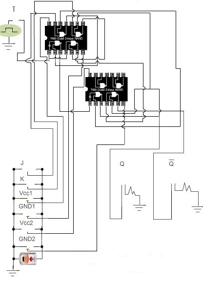
CIRCUIT DIAGRAM